ChipInventor AI Assistant
- Building a funcional ALU
- Using AI to Create the ALU
- Configuring and Testing the ALU
- Simulating the Project
- Synthesizing the Project
- Wrapping Up
Building a funcional ALU
Hello everyone! In this tutorial we’ll focus on how the AI assistant in the ChipInventor platform can streamline your design process. We’ll demonstrate these features by building a functional ALU, but our main goal is to highlight the powerful capabilities of the AI tool and how it simplifies development steps, offering intelligent suggestions and enabling you to quickly prototype digital circuits without getting lost in the details. Let’s explore how AI can transform your design experience!
So, after logging in, click New Project on the navigation bar, and fill in the project details:
-
Name: 16 bits ALU .
-
Description: Implementing an ALU with AI.
-
Type: OpenLane.
Click Create Chip to create the project.
Important: The desired ALU must be capable of performing fundamental 16-bit arithmetic and logic operations, including addition, subtraction, increment, decrement, AND, OR, and NOT. In addition, it must support control signals (zx, nx, zy, ny, f, no) to handle the input data (x, y) and select the appropriate operation, providing consistent outputs for each function.
Using AI to Create the ALU
Let’s create your project using the help from AI, follow these steps:
1. In the workspace, click on the + symbol in the top tab.
2. Select the Generative AI option.
3. In the prompt field, enter the following suggested command:
Create a 16-bit ALU in Verilog with inputs x, y (constant values) and control signals (zx, nx, zy, ny, f, no) to zero/invert the operands and select between AND, OR, addition, and subtraction, using a case block to define the operations. The output should reflect the result adjusted by the no signal. Include a top module that instantiates the ALU.
4. Click Create and wait for the AI to create the block.
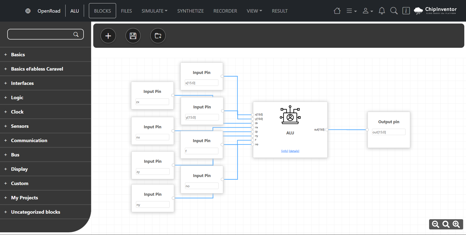
Configuring and Testing the ALU
Now, you have to configure and test if your project is working the right way.
1. Go to the Blocks tab to configure the tests.
2. Add the necessary basic blocks:
- Inputs: Add two blocks to represent the operands x and y.
-
- The input name must be the same as the block ports. (x[15:0], y[15:0], zx, nx, zy, ny, f, no).
-
- Outputs: Add blocks to visualize the results of the operations.
-
- The output name must be the same as the block ports. (out[15:0]).
-
3. Connect the ALU outputs to the output blocks to capture the results
Simulating the Project
1. Go to the Simulate tab and select Dynamic Simulation.
2. The automatically generated code will be loaded for simulation.
3. Click Run to execute:
- Use the interactive menu to change the input values (x, y) and observe the outputs.
4. Control Signals: Configure the signals (zx, nx, zy, ny, f, no) according to the desired operation. For example:
-
Addition: zx=0, nx=0, zy=0, ny=0, f=1, no=0.
-
Subtraction: zx=0, nx=0, zy=0, ny=1, f=1, no=0 (this configuration inverts the value of y before addition).
-
AND: zx=0, nx=0, zy=0, ny=0, f=0, no=0.
-
OR: zx=0, nx=0, zy=0, ny=0, f=0, no=1 (this configuration inverts the result of an AND to achieve OR).
|
zx |
nx |
zy |
ny |
f |
no |
Saída (out) |
|
1 |
0 |
1 |
0 |
1 |
0 |
0 |
|
1 |
1 |
1 |
1 |
1 |
1 |
1 |
|
1 |
1 |
1 |
0 |
1 |
0 |
-1 |
|
0 |
0 |
1 |
1 |
0 |
0 |
x |
|
1 |
1 |
0 |
0 |
0 |
0 |
y |
|
1 |
0 |
1 |
1 |
1 |
1 |
!x |
|
1 |
1 |
0 |
1 |
1 |
1 |
!y |
|
1 |
0 |
1 |
0 |
1 |
1 |
-x |
|
1 |
1 |
0 |
0 |
1 |
1 |
-y |
|
1 |
0 |
1 |
1 |
1 |
0 |
x+1 |
|
1 |
1 |
0 |
1 |
1 |
0 |
y+1 |
|
1 |
0 |
1 |
1 |
0 |
1 |
x-1 |
|
1 |
1 |
0 |
1 |
0 |
1 |
y-1 |
|
0 |
0 |
0 |
0 |
1 |
0 |
x+y |
|
0 |
1 |
0 |
0 |
1 |
1 |
x-y |
|
0 |
0 |
0 |
1 |
1 |
1 |
y-x |
|
0 |
0 |
0 |
0 |
0 |
0 |
x&y |
|
0 |
1 |
0 |
1 |
0 |
0 |
x|y |
Validate the ALU's behavior for each control configuration.
5. Explore other control signal combinations and analyze the results directly in the simulation panel.
6. Test different input and control combinations:
- Addition: x = 5, y = 3.
- Subtraction: x = 7, y = 2.
- AND: x = 0b1100, y = 0b1010.
- OR: x = 0b1100, y = 0b1010.
Note: If you need to check the detailed logic, click on the corresponding wire to view the signals in real-time.
Synthesizing the Project
After testing and validating the ALU through simulation, you can move on to the synthesis stage, where the generated code (HDL) is converted into a physical representation (logic gate networks, blocks, etc.). To do this:
1. Go to the Synthesize tab, where the ChipInventor platform will translate your design into a physical implementation, checking for possible inconsistencies and optimizing the circuit to meet requirements such as area and performance.
2. Click Run Synthesize to start the process:
-
During this stage, warnings or errors related to the design may appear. If that happens, review the blocks and connections in the diagram, correcting any inconsistencies.
-
If everything goes well, the tool will display statistics about the synthesized circuit.
3. In the end, you will have an optimized version of your project, ready for advanced layout and manufacturing steps should you decide to implement it in real hardware.
Wrapping Up
Congratulations! You have learned how to configure and test a functional ALU using ChipInventor. Now you know how to:
-
Use AI to generate functional blocks.
-
Configure inputs and outputs to test different operations in the ALU.
-
Interpret control signals and validate results in the simulator.
Final Challenge: Use the functions learned to create and test new logic circuits, such as a multiplexer or a full adder. Take advantage of ChipInventor's potential to expand your knowledge and consolidate your learning.