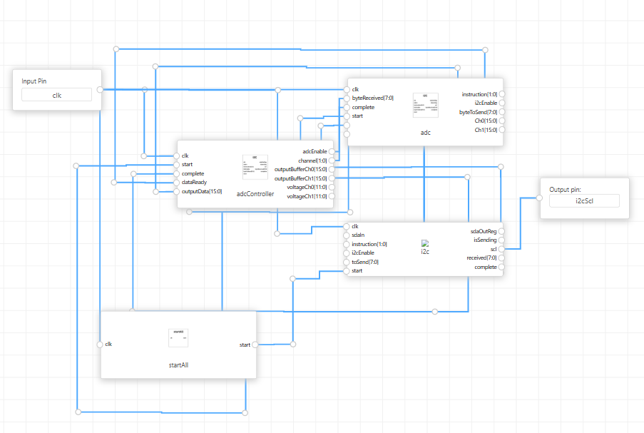
Assembling the Blocks in ChipInventor
Below are the connections that must be made between the blocks:
Block: startAll
- Input:
- clk → System clock.
- Output:
- start → Start signal.
- start → Start signal.
Block: i2c
- Inputs:
- clk → System clock.
- start → Output from startAll block.
- instruction → Operation instruction (write, read, start, or stop).
- i2cEnable → Enable I2C operation.
- byteToSend → Byte to send.
- Outputs:
- scl → I2C clock pin.
- complete → Indicates operation completion.
- byteReceived → Received byte from communication.
Block: adc
- Inputs:
- clk → System clock.
- start → Output from startAll.
- complete → Output from i2c.
- byteReceived → Output from i2c.
- Outputs:
- instruction → Input to i2c.
- i2cEnable → Input to i2c.
- byteToSend → Input to i2c.
- dataReady → Indicates that data has been captured.
- outputData → Data read from the ADC.
- adcEnable, channel → Inputs to adcController.
Block: adcController
- Inputs:
- clk → System clock.
- start → Output from startAll.
- complete → Output from i2c.
- dataReady → Output from adc.
- outputData → Output from adc.
- Outputs:
- adcEnable, channel → Inputs to adc.
- outputBufferCh0 and outputBufferCh1 → Stored data.
- voltageCh0 and voltageCh1 → Converted voltage values.
No Comments