Connecting the Blocks
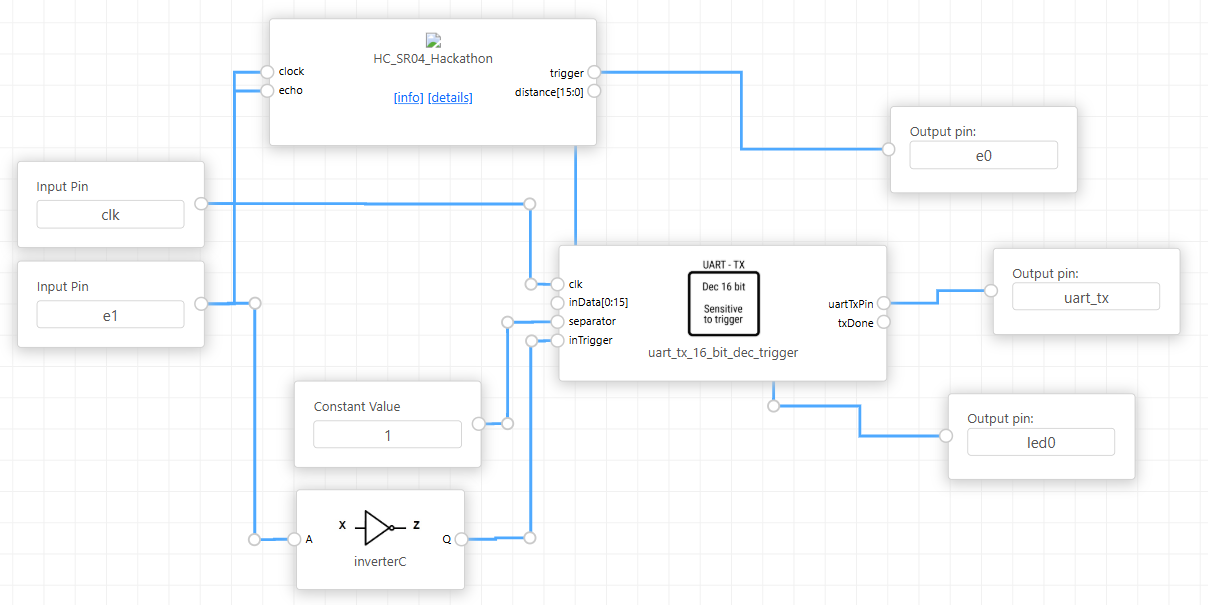
The image shows the following configuration of blocks and connections:
HC_SR04 Block
-
Inputs:
-
clock: Connected to the system clock signal (Input Pin clk).
-
Outputs:
-
echo: Connected to the input pin e1 and to the inverter.
-
trigger: Connected to output pin e0 (physically triggers the HC-SR04 sensor).
-
distance[15:0]: Distance measurement output, sent to uart_tx_16_bit_dec_trigger.
inverterC Block
-
Input (A): Receives the echo signal from the HC_SR04.
-
Output (Z): Connects to the inTrigger input of the uart_tx_16_bit_dec_trigger. The inverter ensures that UART transmission occurs after the Echo pulse ends.
uart_tx_16_bit_dec_trigger Block
-
Inputs:
-
clk: Connected to the system clock (same as HC_SR04).
-
inData[15:0]: Connected to the distance output of the HC_SR04.
-
separator: Receives a constant value of 1.
-
inTrigger: Connected to the inverter output.
-
Outputs:
-
uartTxPin: UART data output, connected to the uartTx pin.
-
txDone: Transmission completion signal, connected to LED led0 to indicate when data has been sent.
No Comments