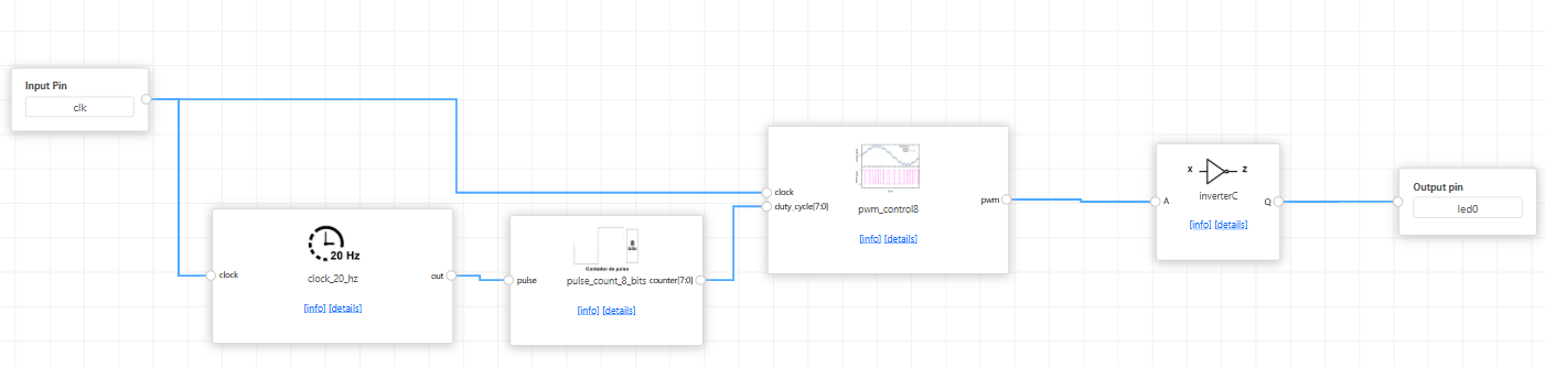
Connecting the Blocks
Below are the connection details between blocks for the project:
clock_20_hz
-
Input:
-
clock: Connected to the system clock input pin clk.
-
Output:
-
out: Connected to the input of the pulse_count_8_bits block.
pulse_count_8_bits
-
Input:
-
pulse: Connected to the output of clock_20_hz.
-
Output:
-
counter[7:0]: Connected to the duty_cycle input of the pwm_control8 block.
pwm_control8
-
Inputs:
-
clock: Connected directly to the system clk pin.
-
duty_cycle[7:0]: Comes from the output of pulse_count_8_bits.
-
Output:
-
pwm: Connected to the A input of the inverterC block.
inverterC
-
Input:
-
A: Receives the PWM signal from pwm_control8.
-
Output:
-
Q: Connected to the output pin l1, which can control an LED.
At the end, your project should be something like this:
No Comments