Building Frequency Dividers
In this section, instead of using an external clock signal, we will manually generate input transitions and define a custom TestBench to verify the behavior of the circuit. The goal is to demonstrate how to create a manual TestBench in Verilog instead of relying on the automated tools provided by ChipInventor.
1. Create a new project.
- Name: Manual TestBench - Frequency Divider
- Description: Manually verifying a frequency divider using a custom TestBench.
- Type: OpenRoad
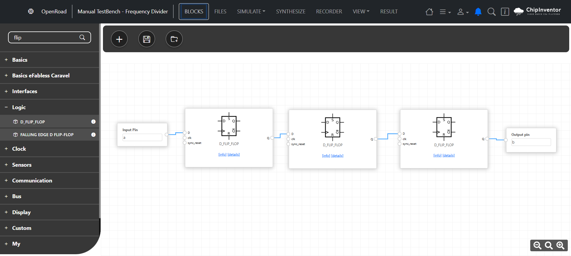
2. Insert multiple Flip-Flop D blocks into the workspace.
- The first Flip-Flop will store the initial state.
- Each additional Flip-Flop will take the previous one’s output as its own clock signal.
3. Connect the Flip-Flops in cascade.
- The Q output of each Flip-Flop should be connected to the D input of the next Flip-Flop.
- No external clock will be used; instead, we will control the D and Reset inputs manually in our TestBench.
No Comments