Writing a Manual TestBench
Since we are not using the automated ChipInventor TestBench, we need to manually define input signals in Verilog to simulate our circuit.
Steps to Write the TestBench:
-
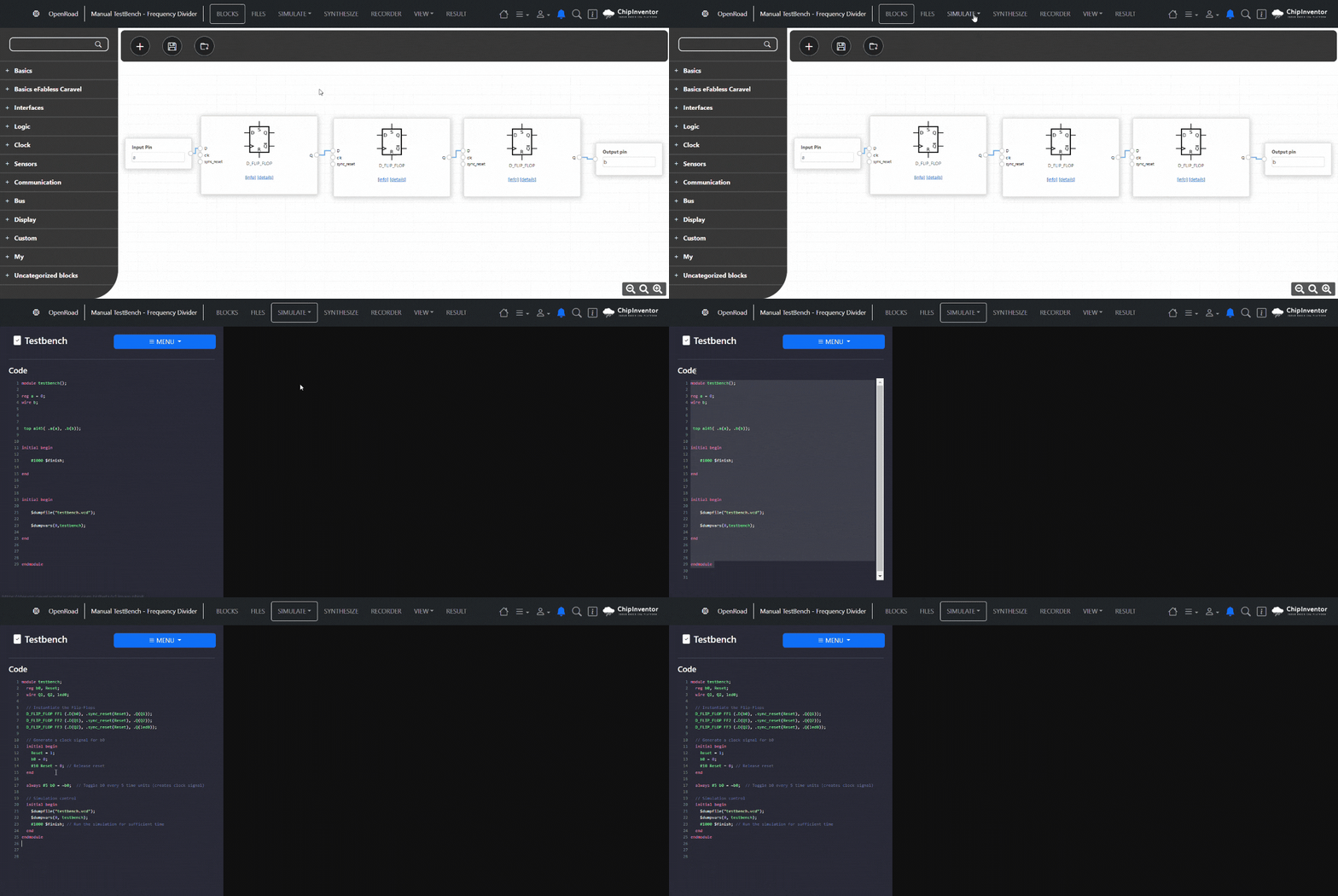
Open the Verilog code editor in the Advanced Simulation tab.
-
Replace the automatically generated code with the following manual TestBench
module testbench;
reg b0, Reset;
wire Q1, Q2, led0;
// Instantiate the Flip-Flops
D_FLIP_FLOP FF1 (.D(b0), .sync_reset(Reset), .Q(Q1));
D_FLIP_FLOP FF2 (.D(Q1), .sync_reset(Reset), .Q(Q2));
D_FLIP_FLOP FF3 (.D(Q2), .sync_reset(Reset), .Q(led0));
// Generate a clock signal for b0
initial begin
Reset = 1;
b0 = 0;
#10 Reset = 0; // Release reset
end
always #5 b0 = ~b0; // Toggle b0 every 5 time units (creates clock signal)
// Simulation control
initial begin
$dumpfile("testbench.vcd");
$dumpvars(0, testbench);
#1000 $finish; // Run the simulation for sufficient time
end
endmodule


No Comments