Project Assembly Steps
2.1 System Inputs
In this step, we identify the essential input signals that enable the motor control system’s operation.
a) Synchronization Clock (clk)
-
Description: Clock signal that synchronizes all operations in the digital system, ensuring all blocks operate in a coordinated manner.
-
Connection: The clk signal must be connected to the main blocks that require precise timing, such as encoder, debouncer, pulse_count16, and pwm_control.
b) Encoder Inputs (IO57 and IO56)
-
Description: Quadrature signals from the encoder used to determine the motor’s current position.
-
IO57 → quadA signal
-
IO56 → quadB signal
-
Function: These signals are processed by the encoder block to calculate the rotation and direction of the motor shaft.
-
Connection: Directly connected to the encoder block.
c) Setpoint Increment Button (key)
-
Description: Physical button used to increase the desired motor position (setpoint), one increment per click.
-
Connection: Connected to the debouncer block, which cleans the signal before sending it to the pulse_count16, responsible for incrementing the setpoint count.
2.2 Input Signal Processing (Debouncers)
Ensuring signal integrity is fundamental for system stability. In this step, we eliminate noise and interference from the physical buttons.
a) Debouncer for the key Button
-
Function: Eliminates bouncing effects (undesired oscillations) on the key button signal.
-
Inputs: clk (synchronization signal) and key (increment button).
-
Output: Clean signal, free of noise, sent to the pulse_count16 responsible for the setpoint.
b) Debouncer for the rst Button
-
Function: Cleans the reset button signal, removing noise that could trigger multiple unintended resets.
-
Inputs: clk and rst.
-
Output: Stable signal connected to the second pulse_count16.

2.3 Defining Setpoint and Reset
In this step, reference values are defined and managed to guide the motor’s position control.
a) Setpoint Counter (pulse_count16)
-
Function: Each pulse received (from the key button) increments the setpoint value, representing the new desired motor position.
-
Input: Directly from the key debouncer.
-
Output: Reference value (rp[15:0]) used in the error calculation.
b) Reset Counter (pulse_count16)
-
Function: Controls reset or adjustment of a second reference parameter, possibly used to reset position values or counters.
-
Input: From the rst button debouncer.
-
Output: Provides an auxiliary value for error calculation or internal resets.
2.4 Reading the Current Position (Encoder)
a) encoder Block
-
Function: Reads the quadA and quadB signals from the incremental encoder and converts them into the motor’s current position.
-
Inputs: clk, IO57 (quadA), and IO56 (quadB).
-
Output: counter[15:0] representing the accumulated pulse count, i.e., the motor’s current position relative to the starting point.
2.5 Position Error Calculation
a) Subtractor (subtractor16signed)
-
Function: Determines the error between the desired position (setpoint) and the motor’s current position.
-
Inputs:
-
rp[15:0]: Reference value from the first pulse_count16.
-
rp[15:0]: Reference value from the second pulse_count16.
-
Output: n[15:0], representing the position error. This value indicates the distance remaining for the motor to reach the target position.

2.6 Proportional Gain Application
a) Proportional Gain (gain16signed)
-
Function: Amplifies the position error, adjusting the control action intensity accordingly.
-
Inputs:
-
n[15:0]: Position error from the subtractor.
-
nb[15:0]: Gain value (e.g., 100).
-
Output: n[15:0], representing the control signal proportional to the error magnitude.
2.7 Summing with Additional Corrections (Optional)
a) Adder (adder16signed)
-
Function: Adds the proportional control value to a fixed correction or to an integral control result (if implemented).
-
Inputs:
-
Proportional control value.
-
A constant (e.g., 0 in this project).
-
Output: Refined control signal for later use.
2.8 Determining the Rotation Direction
a) Comparator (greater16signed)
-
Function: Compares the control signal with zero to determine the motor’s rotation direction.
-
Output: out → 1 (rotates clockwise) or 0 (rotates counterclockwise).

2.9 PWM Duty Cycle Calculation
a) Absolute Module (number_module16)
-
Function: Converts the control signal to its absolute value, removing the sign information since the PWM is always positive.
b) Additional Gain (gain16signed)
-
Function: Adjusts the absolute value with a specific gain to determine the duty cycle’s magnitude.
-
Constant: Example: 10.
c) Saturation (saturation16)
-
Function: Limits the duty cycle value to a maximum of 255 (8 bits), ensuring the pulse width does not exceed the permitted range.
-
Output: n[7:0], which feeds the PWM generator.
2.10 PWM Signal Generation
a) PWM Control (pwm_control8)
-
Function: Generates the PWM signal responsible for motor speed control, based on the previously calculated duty cycle.
-
Inputs: clk and duty_cycle[7:0].
-
Output: pwm, a signal proportional to the desired intensity.
2.11 Direction Control and PWM Application
a) Demux (demux2)
-
Function: Routes the PWM signal to one of two outputs, depending on the calculated rotation direction.
-
Inputs:
-
in: PWM signal from pwm_control.
-
select: Direction signal from greater16signed.
-
Outputs:
-
outa: IO69 → PWM signal for clockwise rotation.
-
outb: IO68 → PWM signal for counterclockwise rotation.
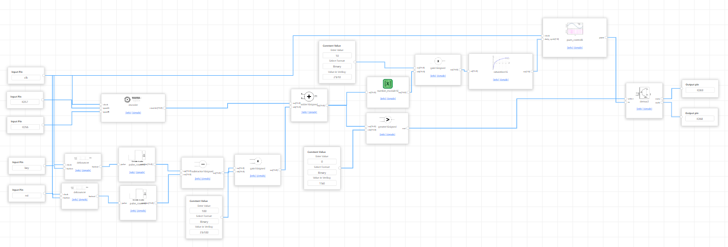
And, at the end, your project should be something like this:
No Comments