Understanding the Project and the Blocks Used
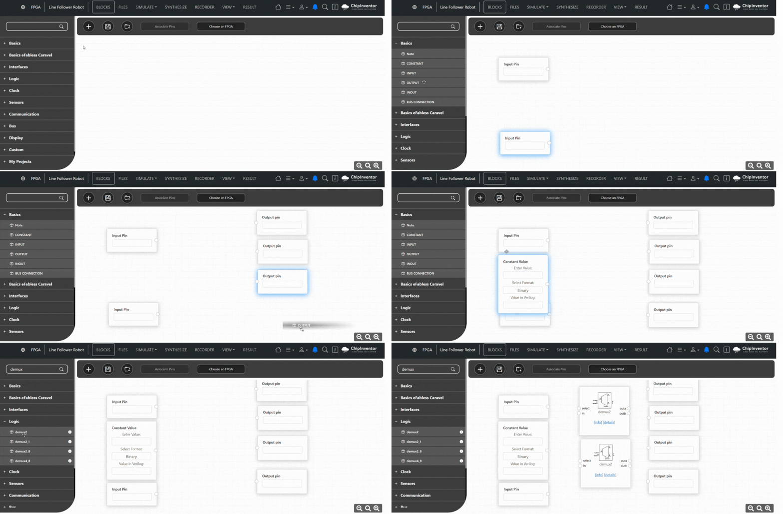
This project implements a line follower robot using an FPGA in ChipInventor. The system processes signals from two line sensors and controls the motors using demultiplexers (DEMUX) based on sensor readings.
Input Pins
-
IO69: This pin receives the signal from the left line sensor. It detects whether the robot is on track by identifying a black line on a white surface.
-
IO68: This pin receives the signal from the right line sensor.
Constant Value
-
A constant logic value 1 represents the activation signal for the motors. It ensures a high logic level is always available for routing by the demultiplexers.
DEMUX Blocks (demux2)
-
Two demux2 blocks are used to control the motors of the robot:
-
They have three inputs:
-
in: The activation signal (logic 1).
-
select: The control signal from the line sensors (IO68 or IO69).
-
clock in: Not used in this configuration (optional in some DEMUX blocks).
-
Outputs:
-
outa: Routes the signal if select = 0.
-
outb: Routes the signal if select = 1.
-
Each demux directs the activation signal to one of its two outputs depending on the line sensor reading.
Output Pins
-
The demux outputs are connected to digital output pins:
-
IO57 and IO56: Controlled by the left motor DEMUX.
-
IO55 and IO54: Controlled by the right motor DEMUX.
-
These pins can be wired to control H-bridges, motor drivers, or directly signal LEDs for testing.


No Comments