Connecting the Blocks
Assemble the project with the following configuration:
uart_rx Block
- Inputs:
- clk → system clock
- uartRx → UART input pin
- Outputs:
- rxByte → connects to the logic block
- byteReady → connects to both the logic block and uart_tx
uart_logic_const Block
- Inputs:
- clk → system clock
- rxByte → from rxByte output of uart_rx
- byteReady → from byteReady output of uart_rx
- compareChar → constant value (e.g., 8’h61 = 'a')
- Output:
- signal → connects to LED (led0)
- signal → connects to LED (led0)
uart_tx Block
- Inputs:
- clk → clock
- reset → button (b0)
- tx_data → receives rxByte from uart_rx
- tx_data_valid → receives byteReady from uart_rx
- Output:
- tx_pin → connects to the UART TX output pin
- tx_data_ready → not used in this simple project
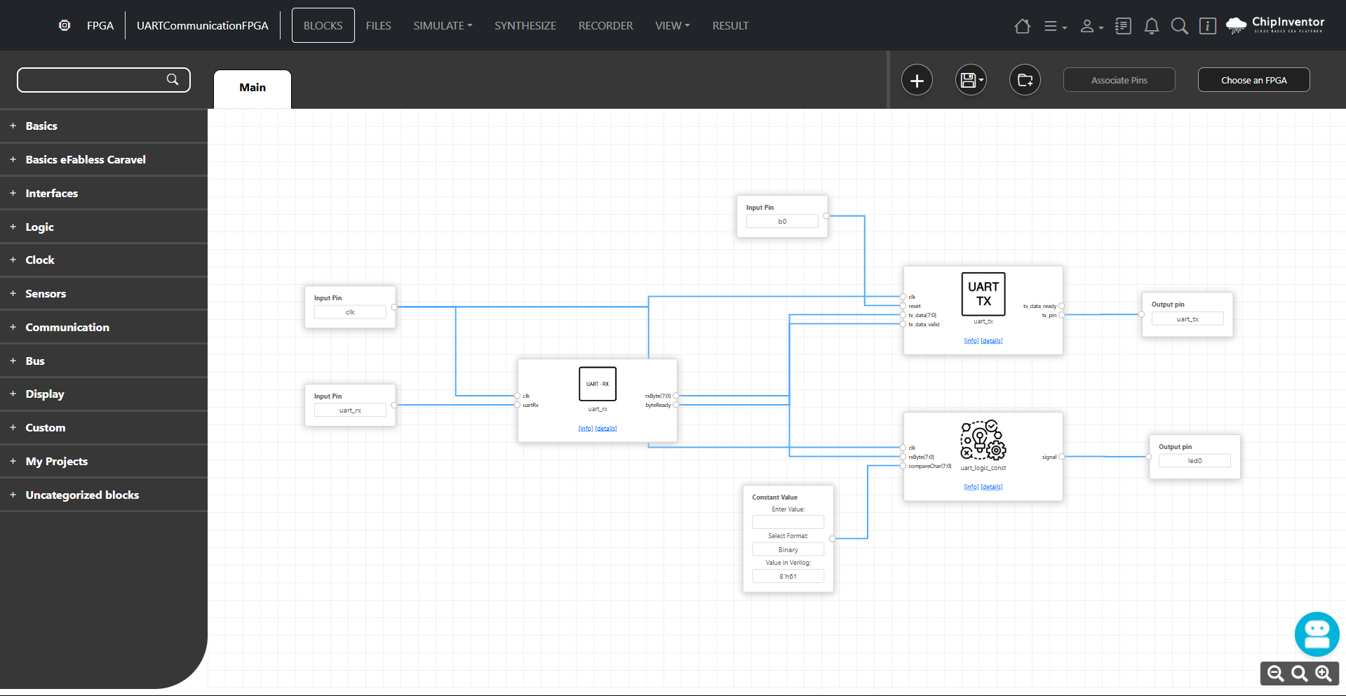
Final Connections:
|
Block/Pin |
Connection |
|
clk |
All blocks |
|
uart_rx |
UART RX input |
|
uart_tx |
UART TX output |
|
b0 |
Reset signal for uart_tx |
|
led0 |
Output from signal of uart_logic_const |
No Comments